LMR-400 cable loss
LMR-400 loses 0.50 dB per 10 m at 144 MHz and 2.17 dB at 2.4 GHz. The part is Times Microwave LMR-400, and every number here is fitted to the attenuation table on its datasheet. Drag the cursor or type a frequency, length and power to read the loss for your run.
LMR-400 loss for 10.0 m, matched
Fit inside the printed tableExtrapolatedDatasheet rowsBand marks (the cursor snaps to them)
Neighbours at 2.40 GHz
Rank 3 of 24 cables with a number at 2.40 GHz, lowest loss first.
Loss chart
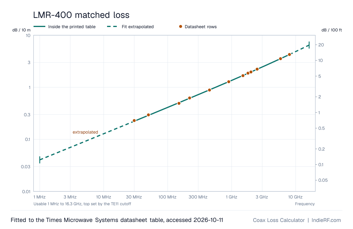
Loss at 144 MHz to 5.8 GHz
| Frequency | dB per 10 m | dB per 100 ft | From |
|---|---|---|---|
| 144 MHz | 0.50 | 1.51 | printed |
| 433 MHz | 0.87 | 2.67 | printed |
| 915 MHz | 1.29 | 3.95 | printed |
| 1.09 GHz | 1.42 | 4.33 | printed |
| 2.4 GHz | 2.17 | 6.62 | printed |
| 5.8 GHz | 3.55 | 10.8 | printed |
Printed means inside the datasheet table. A frequency outside the usable range names the limit instead of a number.
Cross-section
Loss at each band
| Band | dB per 10 m | dB per 100 ft |
|---|---|---|
| 1.8 MHz | 0.05 | 0.17extrapolated |
| 3.5 MHz | 0.08 | 0.23extrapolated |
| 7 MHz | 0.11 | 0.33extrapolated |
| 14 MHz | 0.15 | 0.46extrapolated |
| 28 MHz | 0.22 | 0.66extrapolated |
| 50 MHz | 0.29 | 0.88 |
| 144 MHz | 0.50 | 1.51 |
| 433 MHz | 0.87 | 2.67 |
| 915 MHz | 1.29 | 3.95 |
| 1.57 GHz | 1.73 | 5.27 |
| 2.4 GHz | 2.17 | 6.62 |
| 5.8 GHz | 3.55 | 10.8 |
Matched loss from the fit. A band past the printed table is marked extrapolated. A band outside the usable range names the limit instead of a number.
Datasheet table
| MHz | Printed, dB/100 ft | Fit | Fit − printed | Maker formula |
|---|---|---|---|---|
| 30 | 0.7 | 0.6806 | -0.019 | 0.6776 |
| 50 | 0.9 | 0.8815 | -0.019 | 0.8777 |
| 150 | 1.5 | 1.543 | +0.043 | 1.537 |
| 220 | 1.9 | 1.878 | -0.022 | 1.871 |
| 450 | 2.7 | 2.720 | +0.020 | 2.711 |
| 900 | 3.9 | 3.912 | +0.012 | 3.903 |
| 1500 | 5.1 | 5.136 | +0.036 | 5.126 |
| 1800 | 5.7 | 5.665 | -0.035 | 5.656 |
| 2000 | 6 | 5.997 | -0.003 | 5.989 |
| 2500 | 6.8 | 6.771 | -0.029 | 6.764 |
| 5800 | 10.8 | 10.81 | +0.014 | 10.82 |
| 8000 | 13 | 13.00 | -0.002 | 13.02 |
Times Microwave LMR-400 datasheet, accessed 2026-10-11. Times Microwave LMR-400.
α (dB/m) = a·√f + b·f with f in GHz: a = 0.1275, b = 0.008230. Least squares over the 12 printed rows. RMS miss 0.024 dB/100 ft, largest 0.043 dB/100 ft at 150 MHz.
The sheet's own formula: dB/100 ft = 0.12229·√f + 0.00026·f with f in MHz.
Usable range and build
Printed from 30 MHz to 8 GHz. Usable from 1 MHz to 16.3 GHz; the top is set by the TE11 cutoff. TE11 cutoff 16.3 GHz, from the printed diameters and velocity factor.
- Maker
- Times Microwave Systems
- Impedance
- 50 Ω
- Velocity factor
- 0.85
- Delay
- 3.92 ns/m
- Dielectric
- foam polyethylene
- Centre conductor
- 0.108 in (2.74 mm)
- Dielectric diameter
- 0.285 in (7.24 mm)
- Jacket OD
- 10.29 mm
- Rated maximum
- not printed
- Printed cutoff
- not printed
- Weight
- 0.068 lb/ft
- Bend radius, installed
- 1 in (25.4 mm)
- Bend radius, repeated
- 4 in (102 mm)
- Shield
- Aluminum tape plus tinned copper braid
- Attenuation is printed through 8000 MHz. Above that the fit is extrapolated up to the TE11 cutoff from the printed 0.285 in dielectric and 0.108 in center conductor.
Compare all cablesEvery cable's fit as CSV (CC BY 4.0)Question about this cable, or a correction?